Saturday 31 December 2011

Pat's Creek Trestle

There is very little historical information on the trestle built to span Pat's Creek, but just about everyone who has been to Peace River has travelled right through it. It is, of course, the trestle that you drive under when leaving Highway #2 and coming into the towns main entrance, near the Travellers Motor Inn and the NAR Station... And, yes! There is a creek there but it has been piped and routed underground and now forms part of Peace River's hidden infrastructure.

Google Earth is great!
Pat's Creek is named for a metis man, Patrick Wesley, who owned the land adjacent to the creek in the present day town site. In 1910, after contracting smallpox and being cared for by the Anglican minister's wife, Mr. Wesley passed away, willing 5 acres of his land to the Anglican parish on the condition that he be buried in the shadow of the new church to be built there, the present day site of St. James Cathedral and Athabasca Hall.

Patrick Wesley
I assume that the original trestle was built in early 1916 when the rails reached the location where the station was built. Originally built without the "underpass" feature that allows vehicles to cross, the trestle was modified at a later date to accommodate the highway that followed the creek down from the prairie above. The highway was moved in the late 60's to its present location due to land slides and the old right-of-way now serves as an interpretive walking trail. The creek used to cross under the bridge beside the roadway you see in the photos below until it was diverted underground.

What would I do without "Street view"?

During the period I'm modelling (1979) this was the only entrance from Highway #2 into the southern portion of town. The newer exit off the highway further to the west was, at the time, not a roadway but used by the NAR to cross under the highway to the short switchback that allowed access to the riverside industries along the east bank of the river (on the, unheard of, 6% grade... better have some sand boys).

Did I mention that I really like this Google Earth thing?
I will be modelling the trestle with the Hunterline 81' Pile Trestle kit, two Hunterline Pile Pier craftsman kits and one Micro Engineering 40' deck girder bridge.

Beautiful kits... and Canadian made too!


I haven't started work on this one as yet but I plan to as soon as the Peace and Heart River bridges are ready for track. So, wish me luck (this is my first wood craftsman type construction) and check back on this post for updates.

Mike

Heart River Bridge

Completed in May of 1916, the Heart River bridge was the final link needed to bring rail service to Peace River, then called "Peace River Crossing". Once the trains descend the hill from Judah into the Peace River valley on a grade that fluctuates between 2.4 and 2.9% (at one time, and maybe still, the steepest mainline grade in Canada) the tracks cross the Heart River on the eastern edge of town on a beautiful bridge made up of 11 plate girder spans and a deck truss span for the river itself, all supported by 6 spindly towers that don't look like they should be able to support the weight. In total the bridge is 590 feet long and towers 140 feet above the water.

Preparing to place the last span
Twelve Foot Davis Ball Park at the foot of the bridge

Looking East across the Peace River (see the grade in the bridge?)

1978 - 3 of the 4 NAR SD38-2s headed south
The natural starting point to model this bridge was Micro Engineering's "Tall Steel Viaduct". I used 2 full kits with the 40' connecting spans and another single tower extension. For the deck truss portion, again I turned to the Central Valley Pratt Truss bridge kit as I did with the Peace River bridge, but this time I built it with 5 panels just like the prototype.


I was a little disappointed with the quality of the Micro Engineering kits as compared to the Central Valley kits. The plastic used by M.E. tends to tear and break rather than cut, even when using a new #11 x-acto blade and there are many needless sprue parts that must be cut from the castings. The level of detail was also not as good as I expected. Don't get me wrong, it still produces a very nice model but when building it you must be very careful and take your time. The model does come very close to looking like the real Heart River bridge and captures the over-all "look" of the structure very well with only slight differences that will be difficult for the non-expert to spot.

This picture was taken "upside-down" during construction and flipped. The towers are not yet attached to the girders in the photo.

I modified the kit in several ways: The prototype, as seen in the photos, seems to be built on a gradient (about 1.5 or 2% from what I can tell). So is the model bridge. To incorporate the model's 4% grade I had to build the towers with one side a scale foot and a half taller than the other so that the towers would sit vertically and not look like they were leaning once the bridge was constructed and in place on the layout. This helps mask the relativly steep incline of the bridge.
I also cut the towers to mimic the real bridge's towers, removed the top portion of the towers that support the deck truss span and added supports (I got lucky and found that the height of the top tier of the towers was almost exactly that of the Central Valley kit).
Stiffeners made of wood strip were added to the centre of the two deck girder portions to keep the bridge from sagging.

Bridge on a temporary "land form"
The model bridge measures 42" long and the rails will be 10" above the model river once the foam base is cut down 1". This scales out to 560' long and 133' high (or about 94% of the real bridge)

The bridge turned out even better than I expected and I am very pleased that I was able to capture the over-all look of the real bridge. A few details are yet to be added such as the walkway that ran along the east side of the bridge and the jutting timbers on the west side that carried telephone/telegraph lines across the chasm. The footings for the towers have yet to be installed and the deck still needs actual rails...

I was going to use Micro Engineering's "bridge track" which has guard rails and longer ties that are spaced closer together than normal track but I found that, to install the walkways, the ties were too short and the tie strips included in the Central Valley kits were much better suited to the project. This means, though, that I will have to hand lay the code 55 rail and code 40 guard rails. Thankfully the Central Valley tie strips are built for just such a foolish endeavour.

Like the Peace River bridge posting, I will be adding to this one as work on the bridge progresses, so check back when you can. Thanks.

Mike

Peace River Rail Bridge


The Peace River Rail bridge, along with the iconic auto bridge, will be the centre piece of the whole layout. A faithful reproduction of the two unique bridges will enable the viewer of the layout to immediately recognise that this is Peace River, Alberta.
 
 
View from the air, looking north


Construction of the prototype railway bridge was started in January of 1917 and completed on November 8th, 1918 at the, then, scandalous price of just under $1 million plus a further grant of $175 thousand from the Alberta government to plank the bridge and install railings so that it could be shared with road vehicle traffic. This arrangement lasted until 1968 when the auto bridge was opened.

Post Card from the 1920's, looking east.

The bridge consists of 11 spans: The centre "Through Truss", 3 Deck Truss spans on either side of that and 2 girder bridge approach spans on either bank for a total length of 1736 feet.


Modelling this landmark will present a challenge. I began with Central Valley Pratt Truss Bridge kits. Heavily modified, I can use these to model the main superstructures' 7 spans.

Central Valley Pratt Truss Bridge (Great detail!)

Although the Deck Truss spans of the real bridge consist of 7 "panels" each, the dimensions of the Central Valley kit dictated that I construct the spans with only 6 panels. A compromise that I believe will only be noticeable to the most knowledgeable of viewers.


Other deviations from the prototype are the absence of much of the cross bracing. I decided to leave this out for fear that the model would become too cluttered looking and lose the "airiness" of the prototype. Once the bridge is complete I may decide to add this detail.

So far I have only built 2 of the deck truss spans and these still need to have their walkways added but keep looking back at this post because I will be adding to it as the bridge progresses. Once completed the model will be 103" long and span a complete module and parts of the two adjoining modules, a scale 1373', or 80% of the actual length.


The challenges ahead are how to model the 2 types of unique concrete piers (seen below) that support the bridge and the building of the approach spans on either side of the main structure.


Stay tuned!!!

Friday 18 November 2011

Module Build

Module Build:


     As promised, here is a detailed account of how I built my modules.
The tools needed:

Tape Measure
Drywall T-Square (or large builders square)
Tin Snips (straight cut)
Small clamp
Pencil
Screw gun (#2 Phillips and Robertson bits)
Drill
Bits (5/16", 11/32", 3/8" and small pilot hole bit)
Level
Hammer
Foam compatible adhesive (I use Lapage PL Premium)
Caulking Gun
Long blade utility knife
Spare blades
Wrenches and/or ratchet & socket (9/16", 1/2")
<>

These are the "Rails" that form the long edges of the modules. I use the 2" x 3" size (actual dimensions are 1 3/16" x 2 7/16"). They come in 10' lengths so 2 are necessary to build the 90" modules


I measured the 90" length and marked all three edges using a small square.


With the tin snips I cut the short edges first and then bend the rail and cut the long edge. The long cut will end up slightly curved due to the nature of the tin snips, so I make sure the curve is concave on the piece that will be kept. I need two of these for each module.


Next come the studs themselves. These come in 8' lengths and are nominally narrower than the rails so that they fit inside the rail without distorting the shape. Also, they have holes that allow for the passage of wiring, plumbing and/or stiffeners.


I mark and cut the studs as I did the rails but I cut them slightly shorter than the desired width of the module. In this case 29 3/4" for the desired 30" width. This gives me room to fine tune the width during assembly. I also ensure that each piece has at least one hole for wiring.


Ready for assembly... well almost (if you notice there are only 6 studs... 7 will be needed)


I start the assembly by attaching the end studs to the rails. I put one wafer screw as close to the corner as possible while ensuring that the pieces are flush and near square... remembering to leave a slight (1/8") gap between the end of the stud and the rail. I repeat this on the remaining corners (top and bottom) and make sure that the width of the module is 30" on each side. If I make a mistake I can simply remove the screw, reposition the pieces and re screw.


Once the four corner screws are in, I square the module using my drywall T-Square (a regular building square would also work). I then put a second wafer screw into each corner to lock the module square.


With both ends and both sides secured I set out the cross members. I set the first one 15" from the end of the module (These will be the ones that the legs will eventually be connected to) and the second at 30". The centre cross member I simply put dead centre. These measurements are arbitrary and could really be anything I see fit. When I set out the studs I make sure that the wiring holes are as lined up as possible as this will help when it comes time to wire the module.


Only four screws are necessary to hold each cross members in place. When screwing the cross members I fine tune the width to the desired 30". 


There you have it! One module base. In a future post I will show you how I built the leg structures and attached the foam tops.

Mike

Thursday 6 October 2011

The Prototype


It occurred to me that some of you reading this blog may be unfamiliar with the prototype Northern Alberta Railways so here is a map and some links to web sites that can teach you more about the N.A.R.


The Wikipedia article.


is a short overview of the history of the N.A.R.


is the U of A’s site that will give you access to an in depth history of the early railways that the N.A.R. was made up of and the history of the line once it was formed.


If you wish more information I highly suggest the books “Ribbons of Steel” by Ena Schneider and “North from Edmonton: The Northern Alberta Railways” by Keith Hansen.

And the Booklets "Northern Alberta Railways" volumes 1, 2 and 3. by Colin K. Hatcher and Cecil Swanson.

Happy hunting!
Mike.

Wednesday 5 October 2011

Initial Modules


So far I have built 4 of my module bases: The Peace River Bridge, what I call Peace River Industrial, the Peace River Depot (the corner module) and the Heart River Bridge modules.
I made my module bases out of steel stud and foam tops. Even at 30” by 90” the modules end up being extremely light weight and sturdy. I can lift a 30” by 90” module easily with one hand. By very scientific means (standing on the bathroom scale with and without the module) I weighed a standard 30x90 module, including the legs and cross-braces, and it came out to 20 pounds; 10 pounds for the module and 10 for the legs and braces. I estimate that the completed module will weigh about 5 to 10 pounds more once all the track, wiring, facia, backdrop and scenery items are in place. I find that 25 to 30 pounds per module is still a very manageable weight, especially given the size. This is even lighter than I had expected. I had originally planned to use 2x4 type steel stud (1 ½” x 3 ½”) instead of the 2x3 type (1 ½” x 2 ½”) I ended up building with. Aside from the weight advantage, frames made of this material are ideal for "mobile" layouts because they will not twist, shrink and swell over time like wood will when subject to different moisture levels.
Cutting is easy using tin snips         

The steel stud has proven to be more than sturdy enough to support the weight and be able to handle the stresses of being moved about. Once the 2” Styrofoam top is in place there is very little flexing in the module and with the legs attached there is none at all. This was of paramount importance because the future scenery would not withstand any twisting or bending. The 1/8th inch Masonite I will be using for the facia and backdrop will add even more rigidity to the structure once it is attached. During planning I was afraid that the module centers and ends may droop but they proved to be extremely stiff along their lengths.
Bare Frame        
1x4’s attached to simple 2x2 legs with 1x2 cross-braces make a good stable platform for each module. Given the light weight of the modules I probably could get away with substituting the 1x4’s for 1x2’s but it’s always good to have a little too much than not enough. Each 2x2 leg has a 3/8” hole drilled into the center of the bottom to a depth of about 1 ½”. I hammer a 3/8” tee nut to this hole and use a 1” long 3/8” bolt to allow for fine tuning of the module height. On the head of the bolts I stick self-adhesive felt pads to protect the flooring material. I initially bought these pads at the hardware store but then found them much cheaper at the local “Dollarama”.

Frame on legs (later the cross braces were changed from 2x2 to 1x2)           
The whole assembly is bolted together with 5/16” bolts and wing nuts; 4 bolts attaching the legs to the module frame and 4 more attaching the cross braces to the legs. The cross braces serve two purposes; they stabilize the module against side to side sway and keeping the legs a uniform distance apart. There is some twisting possible in the studs that the legs are attached to and they are not perfectly square to the module in some cases so the cross braces are necessary to correct this.
Completed modules together (cross braces yet to be attached)          
viewed from the backdrop side of the heart river module         

The modules themselves are attached to each other with 2 more 5/16” bolts between the edges of each module to either side of the point where the rails will meet. The layout then becomes even more solid, betraying its flimsy look. I didn’t bother to make the spacing of the interfaces uniform as these modules will always be assembled in this order and configuration.
View from the backdrop side of the Peace River Depot module             
and behind me a very tolerant wife saying "can I have my house back now?"           
I will be building 2 more 30x90 modules shortly and I will document the construction of each in great detail on a future posting so… stay tuned.

Mike

Sunday 2 October 2011

The Vision


     Reading my father's Model Railroader magazines filled me with ideas. From the age of 8 I drew track plans and more track plans... all of which, inspired by the pictures and plans from the magazines. I had no overall goal... only to get the trains running so the plans varied from loops to shelves to basement empires. Burlington Northern seemed to me to be a "neat" prototype, for no other reason than "I liked the colors". Finally, in 1979 Model Railroader published their Clinchfield project railroad and it captivated me... N scale, modular, lightweight, portable, prototypical and well researched! I combed the articles over and over again wanting to absorb it all.
     Christmas of 1980 found us in Vancouver. I was 11, and I convinced my father to take me for a short ride to a hobby shop I had discovered in the small print ads at the back of his magazines. Pacific N Scale in North Vancouver. I couldn't sleep the night before. I imagined a giant store, teaming with display cases and dioramas with all manner of N scale wonders. The shop was actually an 8 foot counter tucked into the back corner of a bookstore with a man behind it. We, the customers, stood in the 30 or so inches between it and small shelves crammed with N scale items... but I was not disappointed.
     This was MY trip to the hobby shop and, for the first time in my life, the clerk addressed ME and not my escort. He showed me great things... Shinohara's prototypical code 70 track and #7 switches were brand new as was the Atlas RS-2 and both were demonstrated to me on a 3 foot length of flex test track set up on the counter. Up until that time my experience with model trains had been that of our Aurora (Trix) "Postage Stamp" F9 growling, jumping and jacking along antiquated sectional track and through our sole turnout which, looking at it now, seems to be about a #2 or #3. This machine was totally different, crawling silently from tie to tie, handrails to scale and details so fine that I had to squint to see them. Before this, if you wanted smooth running N scale engines it involved the destruction and rebuilding of the only two decent mechanisms available (Con-cor's PA-1 and the Trix U-Boat) by a master craftsman who, judging from the articles written about it, had to be a cross between a miniature machinist and the Wizard of Oz. Even then the aesthetics were crude: Molded on details and oversized flanges with very little choice in terms of body styles unless you were the magician mentioned above and could somehow cram the mechanism into your kitbashed body shell.

     I left the little shop (which would one day evolve to become the shop I dreamed of in the form of Pacific Scale Rail in New Westminster) with an arm full of Shinohara products: a dozen lengths of flex track, a 3 switch yard ladder and enough switches to build myself a small shelf switching layout I had been planning. My father left, I believe because of my interactions with the clerk, with the understanding that my passion for the hobby had now eclipsed his and was of great importance to me. Also in hand was the Model Railroader compilation of the Clinchfield series of articles in booklet form with bonus content. It was a "Merry Christmas" indeed! The trip back home to Saskatchewan was very quiet for the rest of my family... I was too busy reading and dreaming to be of any kind of nuisance to anyone.
     I built the small shelf layout on a 7' by 15" length of plywood. CN was the prototype (because that was what my F9 and Bachmann GP-40 were) but the rest was freelanced. "Off the shelf" buildings and rolling stock populated it but it was never finished to the point of scenery as teenaged antics overtook my life before this could be completed. The years went by with not much to do about model railroading aside from the odd "railfanning" here and there. The models were put away and my shelf stood in a corner, unused. I never forgot the dreams I had had; I only set them aside until I would be able to do them justice.
     My move to Red Deer at the age of 19 revived my modeling bug due to the effect of boredom brought on by being separated from my long-time friends. It was at this point that I began to seriously seek out a prototype to follow... Red Deer offered some interesting scenery and operation, Kindersley's CN operations I had a connection with but then... I remembered the grey, yellow and blue of the N.A.R. locomotives as they worked the Peace River valley. So, I researched and the more I researched the more I found that the N.A.R. in the Peace country fit my needs: Unique engines, the short line feel, the interaction with the "Big Boys" (CN and CP), the incredibly interesting operations and scenery in the Peace valley, a rich and colourful history and my personal connections with the railway all intertwined with memories from my childhood. It was perfect!
     So I continued my research and eventually plans were made to fill an 11' by 17' room in the basement. The model would be highlighted by scenes from my younger days of trips to the area and locations of personal importance to me: The gas station in Fawcett my father seemed to always stop at, no matter what time it was. My great grandfather's old mill site that is now the family campgrounds near Donnelly. My great uncles farm at the entrance to Donnelly along with my grandfather’s dealership in town. The alfalfa plant in Falher. My grandfather's homestead and uncle's farm in St. Isadore. The Heart River bridge which, to me as a child, seemed to float in mid-air and, located at the south end of it, a small house that, when I was 4 and 5 years old, I concluded was where my imaginary friend "Johnny Horton" lived (probably because, to me, it seemed inaccessible except by the traversing on foot of the bridge and therefore my sisters would not discover my deceit they so often quizzed me about). Other scenes I wanted to include were in the town of Peace River itself: The KFC by the station that was thought to be such a treat to stop at. Fred's bakery which was fun to open the door of just to get a nose full of the wondrous scents that emanated from it. The gas station by the trestle at the entrance to town which no longer existed and.... without a doubt... the "Dog House" drive-in... which had the soft ice-cream that was the highlight of any trip to "Peace". Further down the line would be Roma, the yard we would fly over on the overpass while traveling back home to High Level and Fairview and High Level's industrial area where I had spent much time watching trains, many years before.

Track plan from 1988
     One scene I wanted to include that was not from my history was the mine at Pine Point, which I had never seen. The "empties in, loads out" operations that I had learned about in the Clinchfield series could be reproduced here, right down to the helix which connected the two ends of the system so that the illusion of empty cars entering the mine and loaded ones coming out could be most effective. Staging was also a large part of the operational scheme in that early plan. I look back on the track plan now and find it surprising that I placed so much importance on this as, at the time, the use of staging in model railroads was a luxury or an afterthought only found on those systems with more than ample space available and used solely by those who demanded realistic operations above all else... which I did not. To me, the recreation of the scene was of utmost importance. The trains and the operation thereof only the setting for those scenes... A means to an end.
     This plan never developed any further than paper as time, space, money and, mostly, women conspired to confine my dreams to the vestibules of my mind. Later, when I was long haul trucking, I filled the endless hours I spent behind the wheel scheming for a way to release these dreams in the form of a real, live model railroad. That was when my current idea for the layout was born.

Current plan showing the module layout
Modules are 30" x 90" 


Actual track arrangement, Peace River, 1979... as far as I can tell
(courtesy Google Earth)
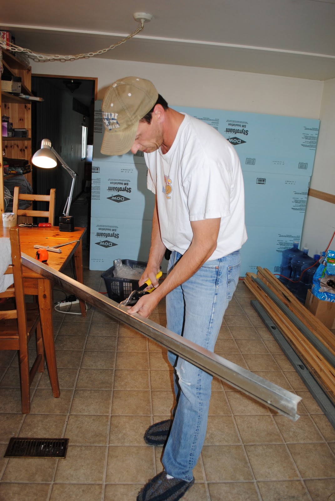
     Again, I reverted to what I had learned from the Clinchfield project. Light weight modules of metal frames and foam scenery, created for display that were easily transported and... STORED!!! Of course!!! I could store my railroad when not in use!!! The answer to the space problem, and transport it to places where I could collaborate with other, like minded, hobbyists (aka "weirdo’s") like me. The options were almost limitless! The concessions I had made in earlier plans could be thrown out the 
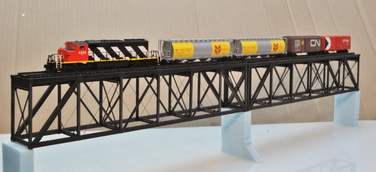
window! No more compressing the Peace River Bridge to 3 feet long or unrealistic scenes, that were supposed to be vast, crammed into little corners, or the omission of vital trackwork because space did not allow. I could have it all; the scenes I wanted, the operations I had neglected, the accurate portrayal of the prototype, the interactions with other modellers and, most of all, the ability to use N scale to its full potential by truly dwarfing the trains with their surroundings.

Mock up of the Peace River modules

Below is a concept drawing of what I would like to accomplish.
(The skirting being the finishing touch) 


Space problem... Solved!

Now... onto other problems...
Time,
Money...
 and, of course, Women... the consumer of both!